Digital FAIR Forms and Ballooned Drawings: Automating AS9102 FAI
Learn how digital FAIR forms and automated ballooned drawings turn AS9102 first article inspection from a manual exercise into a structured, repeatable process with full characteristic accountability.

Digital FAIR Forms and Ballooned Drawings: Automating AS9102 FAI
For most aerospace manufacturers, the slowest and most error-prone part of AS9102 first article inspection (FAI) is not the measurements themselves. It is turning complex drawings into ballooned characteristics and then mapping every requirement into Forms 1, 2, and 3. Digital FAIR forms and automated ballooned drawings target this exact bottleneck, replacing hand-marked prints and Excel templates with a structured, reviewable, and reusable data model.
This article explains how modern tools automate ballooned drawings, populate AS9102 forms, and maintain one-to-one traceability between every drawing requirement and every Form 3 line. It also shows how digital FAIRs support partial and delta FAI, integrate measurement data, and create a foundation for long-term traceability.
For teams putting this topic into daily operation, Connect 981’s aerospace execution solutions, real aerospace execution examples, digital AS9102 FAI help connect the concept to traceability, work-order reality, and audit-ready evidence.
For teams putting this topic into daily operation, digital AS9102 FAI, a connected execution platform help connect the concept to traceability, work-order reality, and audit-ready evidence.
The same operating model also depends on Connect 981’s aerospace operations guidance, practical aerospace operations FAQs, especially when decisions have to move across quality, production, suppliers, and program leadership without losing context.
If you need a broader overview of how these capabilities fit into a full platform, see our AS9102 software overview.
Why Ballooned Drawings and FAIR Forms Are Central to AS9102
AS9102 revolves around a simple idea: every requirement in the design must be clearly identified, measured, and documented. Ballooned drawings and FAIR forms are how that happens in practice.
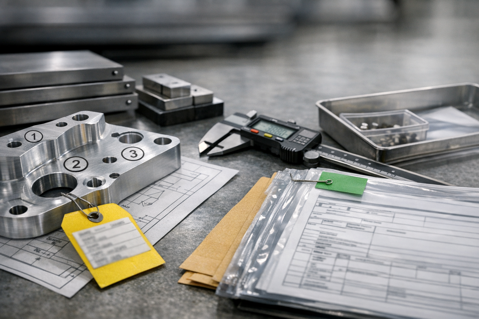
The role of ballooned drawings in capturing every requirement
A ballooned drawing is a drawing where every verifiable requirement is given a unique identifier (a “balloon” number). This typically includes:
- Dimensions and tolerances (linear, angular, diameters, radii, etc.)
- GD&T callouts (position, flatness, perpendicularity, profile, and others)
- Surface finish requirements
- Drawing notes that imply verification (e.g., “NO SHARP EDGES”, “DEBURR ALL EDGES”)
- Material specifications and heat-treat conditions
- Coatings and other special processes that must be verified
Each balloon creates a discrete, traceable “characteristic” that should appear on Form 3. When ballooning is incomplete or inconsistent, characteristic accountability breaks down and AS9102 expectations are not met.
How Forms 1, 2, and 3 relate to the drawing
AS9102 Rev C structures the FAIR into three core forms:
- Form 1 – Part Number Accountability: Identifies the part, configuration, and whether the FAIR is full, partial, or delta.
- Form 2 – Product Accountability: Lists materials, special processes, and functional tests with traceable documentation.
- Form 3 – Characteristic Accountability: Maps every ballooned characteristic to measured or verified results and compatibility evaluations.
The ballooned drawing drives Form 3. Each balloon ID should correspond to exactly one Form 3 line, which then references the same part and revision context defined in Form 1 and the associated materials and processes summarized in Form 2.
Common failure modes in manual FAIR creation
Manual FAI processes typically involve printing drawings, marking balloons with a pen, and populating Excel-based forms. This approach is familiar but fragile. Common problems include:
- Missed or duplicated balloons: Critical dimensions can be skipped entirely or numbered twice, resulting in gaps or conflicts in Form 3.
- Mismatch between drawing and forms: Balloon numbering on paper does not match line numbering in Excel, making reviews and audits difficult.
- Incorrect tolerance or unit interpretation: Values are re-typed manually, increasing the chance of misreading, rounding, or unit mix-ups.
- Weak revision control: FAIRs are completed against one drawing revision while a newer revision is already in effect, but there is no systematic link.
- Heavy reliance on tribal knowledge: Only a few experts know how to balloon in the “right way” or which Excel template applies to which customer.
Digital FAIR tools focus on eliminating these failure modes by treating ballooning and forms as connected, governed data rather than as disconnected documents.
How Digital Tools Automate Ballooned Drawings
Digital ballooning is the starting point for any modern AS9102 workflow. Instead of manually adding balloons on paper, engineers work with digital drawings and software that recognizes and structures characteristics.
Importing PDF and CAD-derived drawings
Most FAI scenarios still rely on 2D drawings, even when the design originates from a 3D CAD model. Effective digital ballooning starts with robust import:
- PDF drawing import: The system ingests released PDF drawings directly from PLM or document control, preserving scaling and clarity.
- CAD-derived drawings: For organizations using model-based workflows, tools may import 2D drawings generated from the 3D model or access published views that carry product manufacturing information (PMI).
- Config-controlled access: The ballooning tool should clearly display the drawing revision and ensure the FAIR is always linked to the correct configuration.
By anchoring ballooning to controlled source files, the risk of using outdated prints is dramatically reduced.
Automated detection of dimensions, GD&T, and notes
Once drawings are imported, modern tools use OCR and pattern recognition to identify potential characteristics:
- Dimension values and tolerances are recognized and tagged as measurement-required characteristics.
- GD&T frames are captured as separate, structured items with their respective datum references.
- Notes that imply verification — such as specific finishing, cleanliness, or edge conditions — can be flagged for inclusion.
Engineers can then review a first-pass extraction rather than ballooning everything from scratch. It is important to view this as assisted extraction, not guaranteed perfection: the software accelerates identification, but quality engineers still verify and adjust the characteristic set before release.
Managing multi-sheet aerospace drawings and numbering
Aerospace parts frequently require multi-sheet drawings with multiple views, detail callouts, and separate notes pages. Digital tools must handle this complexity while preserving clarity:
- Consistent numbering across sheets: Balloon numbers remain unique across all sheets, even when a characteristic is referenced on multiple views.
- Clear sheet and view references: Each characteristic record includes sheet number, view, and zone (if used) to make later reviews straightforward.
- Filters for visibility: Users can filter characteristics by sheet, view, or type (dimension, note, GD&T) to simplify large FAIs.
The outcome is a digital ballooned package where every requirement is visible, numbered, and traceable without the clutter and ambiguity of paper markups.
Designing Effective Digital FAIR Forms
Ballooned drawings create the characteristic structure. Digital FAIR forms turn that structure into an AS9102-compliant report that can be submitted, revised, and audited.
Structuring Forms 1, 2, and 3 for AS9102 Rev C
Digital FAIR tools should mirror the intent and fields of AS9102 Rev C while still being flexible enough to support customer-specific needs. Good practice includes:
- Form 1: Controlled fields for part/assembly number, name, revision, FAIR type (full, partial, delta), and reference documents.
- Form 2: Structured rows for materials, special processes, and functional tests, with clear linkage to certificates, NADCAP scopes, or lab reports.
- Form 3: One row per characteristic with reference to drawing location, requirement, measured result, units, tolerance, and acceptance status.
The software should treat these as data-backed forms rather than static templates, enabling calculated fields, consistent formatting, and robust reporting.
Validation rules that prevent missing or inconsistent data
One of the central advantages of digital FAIRs over spreadsheets is the ability to enforce rules that catch issues before submission. Examples include:
- Mandatory completion of key Form 1 fields (part number, revision, FAIR type, FAI status).
- Automatic warnings if a ballooned characteristic does not have a corresponding Form 3 entry.
- Checks for unit consistency (e.g., preventing inches and millimeters from being mixed for the same characteristic without explicit conversion).
- Flags when measurement results appear outside the declared tolerance range, prompting review.
Instead of discovering issues during customer review, engineers see them while the FAIR is still in preparation.
Prime-specific formats vs a unified data model
Many aerospace suppliers must support different AS9102 formats or overlays requested by primes such as Boeing or Airbus. Manually maintaining separate Excel templates quickly becomes unmanageable. Digital FAIR tools should:
- Maintain a single underlying data model that captures all required AS9102 fields.
- Allow configurable output layouts — for example, one export tailored to a specific customer’s format and another using a standard AS9102 Rev C layout.
- Ensure that regardless of the output style, the same governed data set underpins every FAIR.
This approach avoids having multiple “sources of truth” while still meeting customer-specific presentation requirements.
Ensuring One-to-One Characteristic Accountability
Characteristic accountability is the core of AS9102: for each requirement, there is a clear, auditable link from drawing to measured result. Digital tooling makes this explicit and enforceable.
Mapping each balloon to a unique Form 3 row
In a well-designed system, the characteristic list created during ballooning is the same list used to populate Form 3. Key behaviors include:
- Each balloon ID is represented once and only once on Form 3.
- Characteristics cannot be deleted from Form 3 without equivalent change in the ballooned set, maintaining alignment.
- Renumbering or re-grouping balloons (for example, after engineering review) automatically updates the associated Form 3 lines.
This eliminates the common manual error of mismatched numbering between drawings and forms.
Flagging key and critical characteristics in the data model
Key characteristics (KCs) and critical characteristics (CCs) drive additional scrutiny and may require enhanced sampling or control plans. Digital FAIRs should support:
- Flags on each characteristic indicating whether it is a KC, CC, or other special category as defined by the prime or internal procedures.
- Rules that require additional documentation (e.g., process capability studies) or approvals before a FAIR with CCs can be fully released.
- The ability to report and trend KCs and CCs across multiple FAIRs, lots, or suppliers.
When these flags live in a structured data model instead of free-text notes, quality teams can reliably filter, monitor, and report on safety-critical items.
Bidirectional navigation between drawing and form
One of the most tangible usability benefits of digital FAIRs is the ability to navigate between the ballooned drawing and Form 3:
- Clicking on a Form 3 row highlights the associated balloon on the drawing and brings it into view.
- Selecting a balloon on the drawing jumps directly to the corresponding Form 3 line.
- Filters and search on either side stay in sync, making internal reviews and customer discussions much faster.
This bidirectional link reduces ambiguity and helps reviewers focus on the real question: whether the product meets requirements, not whether the documentation can be interpreted.
Integrating Measurement Data into Digital FAIRs
Once the characteristic structure is in place, the next challenge is getting accurate measurement and verification data into Form 3 efficiently and correctly.
Capturing manual measurements accurately
Many FAIs still involve manual measurements taken with calipers, micrometers, height gages, or simple gauges. Digital FAIR tools should support:
- Guided data entry forms that show the requirement, nominal, and tolerance alongside an input field for the actual result.
- On-the-spot validation to catch obvious mis-keys (e.g., a value an order of magnitude off expected nominal).
- Direct association of who measured, when, and with which instrument, if required by internal or customer procedures.
The goal is to eliminate re-keying from handwritten sheets into Excel and instead have measurement data recorded once, in the system of record.
Importing CMM and other automated inspection data
For complex components, automated inspection systems (CMMs, vision systems, laser scanners) often generate result files in standardized formats. A mature digital FAIR workflow:
- Maps result file feature IDs to Form 3 characteristic IDs, ensuring that data flows to the correct line.
- Handles multiple runs or samples, summarizing results as required by the AS9102 form while retaining detailed data behind the scenes.
- Allows selective review, so engineers can quickly focus on out-of-tolerance or near-limit conditions.
This tight linkage between inspection systems and FAIRs removes transcription errors and accelerates report completion.
Handling units, tolerances, and compatibility evaluations
AS9102 Form 3 requires more than just recording numbers. It also demands a clear compatibility evaluation that confirms whether the characteristic is acceptable. Digital FAIR tools help by:
- Standardizing units and enforcing conversions where needed, so a drawing in inches and a CMM report in millimeters remain consistent.
- Structuring tolerance formats (e.g., bilateral, unilateral, limit) so calculations can be automated and consistently interpreted.
- Providing explicit fields where engineers record compatibility or attach supporting notes for borderline cases.
Instead of interpreting free-text comments during an audit, reviewers see structured results together with a clear pass/fail or compatible/not compatible conclusion.
Reuse and Change Management with Digital FAIR Structures
AS9102 Rev C recognizes that not every event requires a completely new, full FAIR. Digital FAIR structures make it practical to reuse characteristic sets and manage partial or delta FAI without losing traceability.
Reusing balloon and characteristic structures across builds
Once a part number has been fully ballooned and its characteristics validated, that structure becomes a reusable asset:
- New FAIRs for repeat builds can leverage the same ballooning, avoiding repeated engineering effort.
- Suppliers or additional plants can inherit an approved characteristic set, reducing variation in interpretation.
- Updates to the drawing trigger incremental reviews instead of new ballooning from scratch.
This reuse is only safe if revision control is handled carefully, which is where digital tooling excels compared to file-based workflows.
Supporting partial and delta FAI without recreating forms
Partial and delta FAIs are often the most confusing for teams using spreadsheets. Digital FAIR tools can make them routine by:
- Allowing Form 1 to explicitly flag FAIR type (full, partial, delta) as required by AS9102 Rev C.
- Duplicating the baseline FAIR structure and then highlighting only those characteristics that must be re-verified.
- Maintaining a link back to the original FAIR so reviewers see the complete history at a glance.
Instead of building a new spreadsheet for every change, teams extend a controlled data set and capture exactly what has changed and why.
Maintaining traceability across revisions and submissions
Traceability in digital FAI spans more than just drawing revisions:
- Each FAIR is linked to the drawing revision, associated change notices, and the specific production lot or serial numbers inspected.
- Subsequent FAIRs (for example, after a process move or design modification) explicitly reference the earlier baseline FAIR.
- Systems can provide a “family tree” of FAIRs showing how the part has evolved and when verification was repeated.
This level of traceability is extremely difficult to maintain using independent Excel files stored on shared drives. Digital FAIR tools make it a natural byproduct of everyday work.
How Digital FAIRs Fit into a Broader AS9102 Software Strategy
Digital FAIR forms and ballooned drawings are the engine of AS9102 documentation, but they rarely live in isolation. When they are integrated into a broader AS9102 software approach, organizations gain:
- Automatic population of part, revision, and purchase order data from ERP or PLM.
- Alignment of FAIRs with shop-floor execution, work instructions, and quality checks.
- Centralized storage and search for all FAIRs, measurement results, and supporting documents.
To understand how these elements span planning, execution, and audit readiness, it is useful to step back and review an AS9102 software overview that covers workflow orchestration, integration, and analytics on top of the digital FAIR foundation.
Practical Steps to Implement Digital FAIR Forms and Ballooned Drawings
Organizations moving from manual to digital FAI can take a phased approach focused on risk reduction and quick wins.
- Start with high-impact parts: Select parts with complex drawings, high characteristic counts, or a history of FAIR rework.
- Digitize ballooning: Implement automated ballooning for those parts, validating extraction rules and review practices.
- Standardize AS9102 forms: Configure Forms 1, 2, and 3 templates aligned with Rev C and major customer overlays.
- Integrate measurement data: Pilot CMM and manual data capture flows for a subset of characteristics.
- Introduce partial/delta FAI logic: Once the baseline FAIR is stable, use the same structure to manage engineering changes.
By proving value on a manageable scope first, teams build confidence and templates that can scale across programs, sites, and suppliers.
Conclusion
Digital FAIR forms and automated ballooned drawings transform AS9102 FAI from a manual document-creation activity into a governed, reusable data process. By automating characteristic extraction, enforcing one-to-one mapping between balloons and Form 3, and integrating measurement data, quality and manufacturing teams can reduce cycle time, lower error rates, and strengthen traceability.
When these capabilities are connected to broader AS9102 software workflows, they become a foundation for aerospace compliance, audit readiness, and continuous improvement. The practical next step is to identify where manual ballooning and spreadsheet-based FAIRs are causing the most pain, and then pilot a digital FAIR approach that directly addresses those bottlenecks.


Related Blog

Built for Speed, Trusted by Experts
Whether you're managing 1 site or 100, Connect 981 adapts to your environment and scales with your needs—without the complexity of traditional systems.
